[ad_1]
Serial Peripheral Interface (SPI) is not really a protocol, but more of a general idea. It’s the bare-minimum way to transfer a lot of data between two chips as quickly as possible, and for that reason alone, it’s one of my favorites. But that doesn’t mean that everything is hugs and daffodils. Even despite SPI’s simplicity, there are still a few ways that things can go wrong.
In the previous article in this series, inspired by actual reader questions, I looked into troubleshooting asynchronous serial connections. Now that you’ve got that working, it’s time to step up to debugging your SPI bus! After a brief overview of the system, we’ll get into how to diagnose SPI, and how to fix it.
What is SPI?
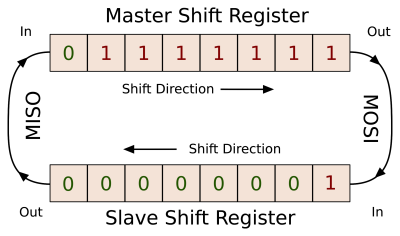 The core idea of SPI is that each device has a shift-register that it can use to send or receive a byte of data. These two shift registers are connected together in a ring, the output of one going to the input of the other and vice-versa. One device, the master, controls the common clock signal that makes sure that each register shifts one bit in just exactly as the other is shifting one bit out (and vice-versa). It’s hard to get simpler than that.
It’s this simplicity that makes SPI fast. While asynchronous serial communications can run in the hundred-of-thousands of bits per second, SPI is usually good for ten megabits per second or more. You often see asynchronous serial between man and machine, because people are fairly slow. But between machine and machine, it’s going to be SPI or I2C (and that’s the next article).
 Turning this pair of shift registers into a full-blown data bus involves a couple more wires, so let’s look into that now, and cover the labelling of these wires as we go. The master controls the clock (CLK or SCK) line, that’s shared among all of the devices on the bus. Instead of a simple ring as drawn above, the master’s shift register is effectively in a ring with each of the slave devices, and the lines making up this ring are labelled MISO (“master-in, slave-out”) and MOSI (“master-out, slave-in”) depending on the direction of data flow.
Since all of the rings are shared, each slave has an additional dedicated line that tells it when to attach and detach from the bus. That is, each slave has a slave-select (SS or sometimes called chip-select CS) line, and when it’s high, the slave disconnects its MISO line, and ignores what comes in over MOSI. When the individual SS line is pulled low, the slave engages. Note that the master is responsible for keeping one and only one SS line active low at any given time.
Typical SPI Communication:
- The master pulls the slave’s personal slave-select line low, at which point the slave wakes up, starts listening, and connects to the MISO line. Depending on the phase (covered in detail just below) both chips may also set up their first bit of output.
- The master sends the first clock pulse and the first bit of data moves from master to slave (along MOSI) and from slave to master (along MISO).
- The master keeps cycling the clock, bits are traded, and after eight bits, both sides read in the received data and queue up the next byte for transmission.
- After a number of bytes are traded this way, the master again drives the SS line high and the slave disengages.
 Here’s a concrete transaction, between a microcontroller master and a 25LC256 SPI EEPROM. First, the master drops the CS line. Then it starts clocking in the command — in this case binary
 00000011, the read command. The next two bytes from the master are the read address. All the while, the slave has been holding its MISO line low, returning zeros. After receiving the read address, the slave starts sending back its data. In the case of this EEPROM, it will keep sending sequential bytes until the master stops clocking and raises the CS line, ending the transaction.
Looks easy enough when it’s working!
Phase and Polarity
Here’s the number-one problem with SPI lines, and the first place to look if you’re troubleshooting. If you look carefully at the traces above, you’ll notice that both chips pushed their data out on the MISO/MOSI lines at the falling edge of a clock cycle. What you can’t see, but you could probably guess, is that they both read in on the rising edge — right in the middle of a clock period.

The choice of which edge to read data on, as well as whether the clock signal idles high or low, presents two binary variables that can change from one chip to the next, giving us four different “versions” of SPI. The idle state of the clock signal is called clock polarity, and it’s easy to explain. A clock that idles high has a polarity = 1, and vice-versa.
Unfortunately, if you like thinking about when in the clock cycle the chip reads the data, the industry decided to latch on to another aspect of the transmission which maps to the same thing: the phase. Phase describes whether the data is going to be read on the first clock transition (phase = 0) or the second (phase = 1). If the clock idles low (polarity = 0) the first transition is going to be upward, so a system that samples on the upswing will have phase = 0. If the clock idled low, however, the first transition is necessarily down, so a system that samples on the upswing will have phase = 1 — sampling on the second transition. My head hurts even writing it out.
Here’s how I cope. First, I look at when the data is sampled. If data is sampled on the upwards clock edge, the phase equals the polarity, otherwise it’s the opposite. A read-on-rising-edge is 0,0 or 1,1. And since the polarity makes sense, it’s easy to pick between the two. If it idles low, you have 0,0.
| Sample on Rising Edge | Sample on Falling Edge | |
|---|---|---|
|
Clock Idles Low |
Phase: 0 Polarity: 0 |
Phase: 1 Polarity: 0 |
|
Clock Idles High |
Phase: 1 Polarity: 1 |
Phase: 0 Polarity: 1 |
Most everyone uses 0,0 or 1,1: data is read on the upward-going edge, and reset on the downswing. Some devices are picky about which of these two you’re using, while others aren’t. For instance, the Microchip 25LCxxx series of SPI memories samples on the upswing and doesn’t care at all about how the clock idles. That’s my kind of chip.
Where this ends up, if you’re too lazy to read the datasheet or if you’re reverse-engineering, is a four-way choice. If it’s your only variable, it’s not hard to brute-force. Most chips have a status register or a chip ID. Set the phase and polarity on your microcontroller, and send the command to read the known data out of the slave device, and verify the answer. If phase and polarity is your only problem, you’ll have the right configuration in a jiffy. If your problems run deeper, you’ll have to move on. And if you don’t have the datasheet, you’ve got four times the work to do, so get this right if you can.
Speed
Because SPI is clocked, and the slave-select line delimits a conversation, there’s not much that can go wrong in syncronizing two devices. Not much, except when the master talks too fast for the slave to follow. The good news? This is easy to debug.
For debugging purposes, there’s nothing to lose by going slow. Nearly every chip that can handle SPI data at 10 MHz can handle it at 100 kHz as well. (If you know exceptions, post up in the comments!) On the other hand, due to all sorts of real-world issues with voltages propagating from one side of a wire to another and the chip’s ability to push current into the wire to overcome its parasitic capacitance, the maximum speed at which your system can run is variable. For really high SPI speeds (say, 100 MHz and above?) your system design may be the limiting factor.
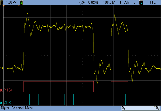
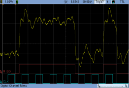
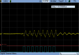
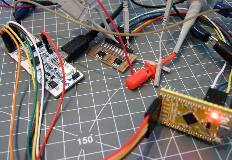
So test it. Start slowly and work your way up until you start noticing errors, and then back off. I’ve never had problems with short lines at 10 MHz, but you never know. The images here are from the EEPROM, which is rated for 10 MHz, soldered on a sketchy breakout board and connected through a bunch of 20 cm (8″) DuPont cables. You can see it meeting (just barely) the requirements at 9 MHz, but lagging at 18 MHz. At 35 MHz, it can’t even switch the line fast enough to produce any signal at all.
More Clocking!
If you’re sending a command to an SPI slave and expecting an answer that never comes, double-check that the master is continuing to toggle the clock until the slave is done.
This can be counter-intuitive, but remember how SPI works — it’s a ring of shift-registers. To get data out of the slave’s shift register and into the master (and vice-versa) there needs to be clock pulses. The master is responsible for sending this clock, and knowing how long it needs to toggle the clock.
For the EEPROM I’m using as a demo, it will continue to spit out sequential bytes until the clock stops. Most memories work this way. But other devices, like temperature sensors, will often only return a byte or two. If you keep clocking after that, they often return all zeros. When the slave must return a variable-length packet, it can either transmit the expected length first, or send bytes terminated with an end-of-data marker. This is all higher-layer stuff. I just want you to remember that if you want data back from the slave, you have to give it a clock.
Bus Problems
So far, I’ve been considering what can go wrong for each individual slave on the bus. If you add more devices to the bus (each with their own CS line, but sharing CLK, MISO, and MOSI) things can get hairy. In principle, all devices have tri-state drivers for their output lines so that they can pull it high or low, and detach when necessary. In principle, devices never speak (transmit on the MISO line) except when they’re spoken to (their CS is dropped low by the master). In theory, everything works out just fine.
Switching Phase and Polarity
Remember the four possible combinations of phase and polarity? That goes for each device on your bus. Keeping track of which device is being spoken to and setting a couple configuration bits isn’t hard, it’s just that you can’t forget to do it. Demonstrate to yourself that you can talk to all of the devices already on the bus each time you add a new one. And if you ever change modes, start writing the code you’ll need to change back.
Bad Actors
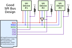 The master can only address one slave at a time. If you’re getting garbage across MISO, make sure that only one CS line is asserted low at a time. If that’s the case, it’s conceivable that one of the slaves is misbehaving. You can try unplugging devices one at a time until you find the culprit.
[Paul Stoffregen] was having trouble with SPI compatibility on the Arduino platform due to slaves that weren’t releasing the MISO line. His solution is to add a tri-state buffer chip to the offending device, and tie the tri-state line to the chip’s CS line, so that it can never tie down the MOSI line except when it’s being used. This is a great solution to the problem.
Open Collectors
While some slaves drive the MISO line too much, others drive it too little. In particular some slave devices may fail to pull up the MISO line, scrimping on one transistor and only pulling the line down. If this is the case, the MISO line might need a pull-up resistor attached. Again, this is non-standard, but is for instance true of SD-MMC memory cards that use the SPI-like interface. By adding pull-up resistors to the MISO line, you can pretend that it’s SPI.
The Test
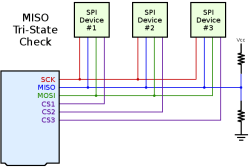
To test for MISO-line problems, both bad actors and open collectors, you can temporarily attach a pair of (say) 100 kOhm resistors to the line, one to VCC and one to GND, serving as a weak bias to the mid-rail voltage. Put all the CS lines high, so the slaves should detach from the bus. If any chip is failing to tri-state, you’ll see the line pulled up or down when it should be resting in the middle. Those are the bad actors. Now run the bus. If a chip can only pull the line down, you’ll see what looks like valid data, but it will vary between mid-rail and GND instead of VCC and GND. There’s your open collectors.
Initialization
Not unrelated, what happens when the microcontroller that serves as your SPI bus master is just booting up? The voltage levels on the SPI bus (and the CS lines) are floating — essentially random. The clock line might pick up power-line signals and oscillate at 50 or 60 Hz, and some chips might start talking to each other, or get into strange states, before the micro asserts control.
For this reason, some people advocate (weak) pullup resistors on the CS lines, so that even before the microcontroller is up and running, all of the SPI devices are de-selected. You might think that this is a power-waster, but since the CS lines idle high anyway, the resistors only conduct when a chip is selected. I’ve never had trouble bringing SPI chips up from power-down myself, but give it a shot if you experience odd behavior on startup.
Summary
Debugging a broken SPI bus isn’t actually that hard. Since the lines are unambiguously named (CLK, MISO, MOSI) you don’t have to think very hard when wiring the circuit up, but double-check your wiring anyway. Most of the time, you’ll have the configured phase and polarity incorrectly, which can be solved with an oscilloscope and a peek into the datasheet. After that, it might be a speed issue, which is easily fixed by just slowing down until it works and troubleshooting from there. You are clocking the slave’s data out, right?
If you’ve got a bus of SPI devices, you can troubleshoot each one individually, as long as they’re behaving. Pulling the MISO line weakly to mid-rail and seeing if it stays there can verify that they are. And don’t forget to switch modes between slaves if you need to.
If you’re using an SD-MMC card, or if all else fails, or if you’re just somehow superstitious, you can try adding pull-up resistors to various lines to stabilize them during power-up or for some other magical reasons. SPI should be a bus with push-pull drivers on all sides, so you shouldn’t need pull-ups. But then again, your bus should also be working.
As always, I’d love to hear your SPI debugging tips, tricks, and horror stories!
[ad_2]
Source link

